ARMY TM 5-5420-212-23
MARINE CORPS TM 08676A-23/2
(2) LEVELLING SCREWS. Used to level adjustable support. Screws should be adjusted to bring the posts as close to
vertical as is possible, but with a 1/4 in (6 mm) gap between one leveling screw and the baseplate screw hole.
(3) POSTS. Guides in which the roller beam/capsill can be moved up or down.
(4) SUPPORT PIN HOLES. Used to position roller beam and jackseat at different heights.
CAUTION
Jackseat must not be placed on pins in holes 4, 5, or 6.
(5) HOOKS. For connecting upper part of cross girder to support.
(6) SHOOT BOLTS. For connecting bottom part of cross girder to support.
(7) SUPPORT PINS. Two pins on each side of support permit changing height of roller beam/capsill and jack seat.
(8) IDENTIFICATION PLATE. The component serial number is marked on this plate.
(5)
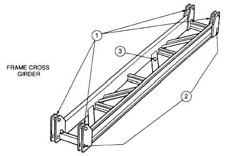
Frame Cross Girder
The frame cross girder is used to space and maintain distance between adjustable supports.
(1) DOWEL. Fits in hooks on post of adjustable support.
(2) SHOOT BOLT HOLES. Shoot bolts of adjustable support go through these holes to lock girder to support.
(3) IDENTIFICATION PLATE. The component serial number is marked .on this plate.
1-22


